Pinctrl on STM32MP135F
Intro
Bringing up a peripheral on a Linux based board usually starts with pin configuration, you route the right CPU pins to the peripheral you want to use. For example, when you connect your workstation to the board's UART, the pins wired to RX and TX must be multiplexed to the UART controller inside the SoC.
But pin muxing is only part of the story. Each pin also has electrical settings pull-ups/pull-downs, drive type, slew rate, and more. That's where the Linux pinctrl subsystem comes in: it provides a common way to describe and apply pin multiplexing and pin configuration from the device tree.
In this article, we'll walk through how pin configuration works on the STM32MP135F and how you can use it, so without further ado, let’s start.
Theory
Pinctrl is a Linux subsystem (you'll find it under drivers/pinctrl/) whose job is to let you configure various pin settings. But before we use pinctrl, we should clarify a few things, what a pin is and what it's for and what whole pin multiplexing actually means?
If we look at an older CPU such as the Intel 4004, we can see that it was packaged in a DIP format. This means it had two parallel rows of metal leads underneath the chip, commonly called pins:
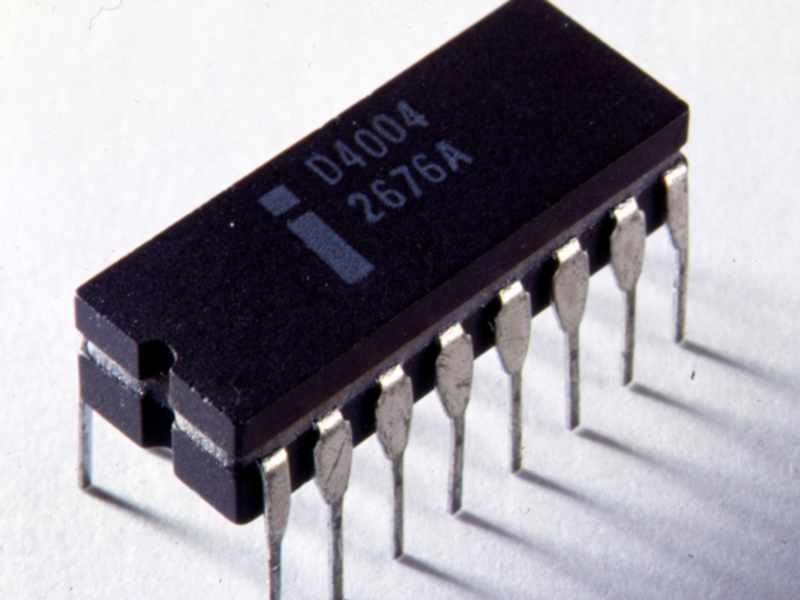
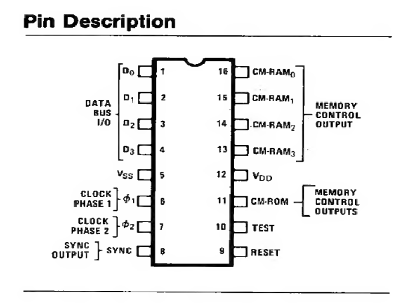
Over time, the amount of electronics we can fit on a single chip has grown dramatically, and CPU capabilities began to outpace the number of pins available in the package. This pushed CPU manufacturers toward a technique called pin multiplexing. Pin multiplexing means reusing the same pins for more than one function at different times. For example, on the Intel 4004, the same pins could be used to fetch code from ROM and later store results in RAM. Electrically, ROM and RAM shared the same bus, and the CPU controlled when the pins should be interpreted as data coming from ROM versus data going to/from RAM.
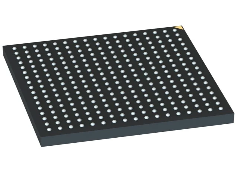
On modern CPUs, we don't have long pins sticking out of the chip; instead, we have pads or balls soldered to the board. But the idea remains the same: the CPU contains more circuitry than it can expose through package pins, so we need a way to assign alternate functions to them.
I'd like to clarify one more thing here: pin numbering. In DIP-packaged chips, pins are numbered sequentially, starting from one end. For example, on the Intel 4004 the pins are numbered 1, 2, 3, 4, 5, and so on, up to 16.
In modern CPUs, numbering is usually based on a grid, similar to a chessboard, for example A2 or C3:
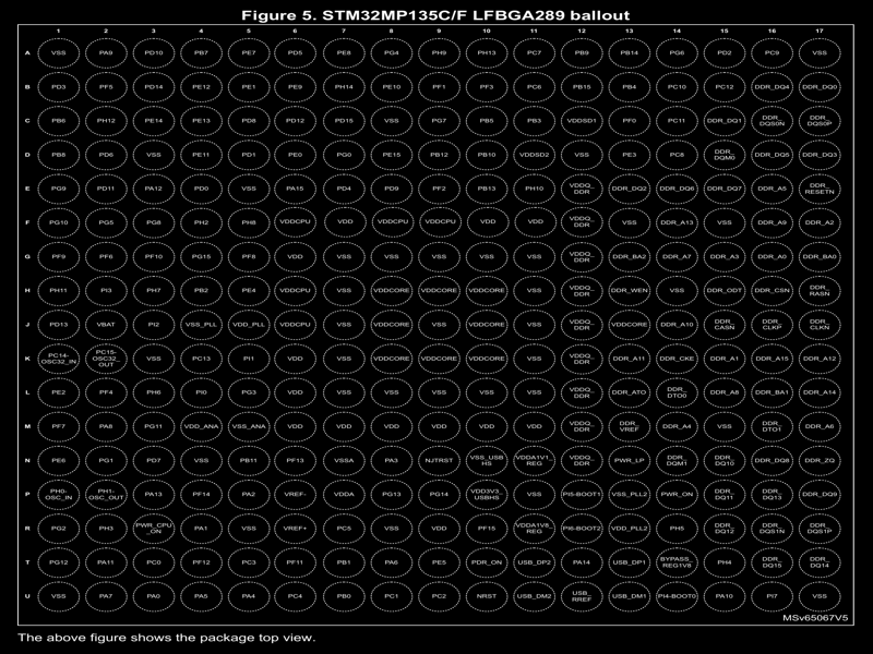
In the datasheet for the STM32MP135F-DK board, we can find the mapping between physical balls and their functions. For example, ball L3 in the grid layout is connected to the following circuits: GPIOH6, TIM12_CH1, USART2_CK, I2C5_SDA, SPI2_SCK/I2S2_CK, QUADSPI_BK1_IO2, ETH1_PHY_INTN, ETH1_MII_RX_ER, ETH2_MII_RXD2/ETH2_RGMII_RXD2, and QUADSPI_BK1_NCS. Which of these circuits is active depends on the alternate function selected for the ball. By default, all GPIOs on the STM32 CPU are configured as GPIO, which is convenient cause we can use GPIO pins numbers instead of balls numbered when we are talking about the pins.
Not all pins have alternate functions. For example, A1 is wired only to GND, M6 is wired only to PWR for the whole chip, and F6 is wired only to PWR for the CPU subsystem etc.
Configuring L3 for an alternate function starts with understanding which GPIO pin it is connected to by default. From the board datasheet, we can see that it is connected to GPIOH6 (written as PH6, which means GPIOH6). The base address of the GPIOH register is 0x50009000, and setting bits 12 and 13 puts the pin into alternate function mode. Once the GPIO is in alternate function mode, we can select the specific function by writing to the AFRL register at offset 0x20. For example, to set GPIOH6 to TIM12_CH1 we would write 1 to bits 12–15 of 0x50009000+0x20; for USART2_CK we would write 2; for I2C4_SDA we would write 3, and so on.
Besides configuring alternate functions for a pin, the CPU also supports other features such as pull-up/pull-down resistors, signal speed, and open-drain or push-pull output for each GPIO pin. Let's walk threw these settings and explain what each of them actually does.
A pull-up resistor brings the voltage to a high state, while a pull-down resistor brings it to a low state; it's pretty straightforward.
Speed is a bit more complicated. The speed of a pin is indirectly related to its impedance: when speed is high, impedance is low; when speed is low, impedance is high. If the term impedance is unclear, think of it like a door: light doors are easy to move and can switch quickly between open and close state(low impedance), while very heavy doors require much more effort and time to move between states (high impedance). Low impedance is useful when we need fast signals, because changes in voltage level do not require much current. Hih impedance is useful when we need to reduce signal ringing, which may occur when components are poorly impedance-matched. As a rule of thumb, start with the lowest speed that supports your signal and increase it only if higher impedance degrades the signal too much.
The last options are open‑drain and push‑pull, which control how a pin drives a signal in output mode. In push‑pull mode, setting the pin to 0 actively drives it low by connecting it to GND, while setting it to 1 actively drives it high by connecting it to a supply rail (for example, 3.3 V). In both cases, the signal is actively driven. In contrast, open‑drain mode can only actively drive the signal low. When it is not driven low, the pin is left floating, meaning it is not connected to any rail or resistor. For this reason, open‑drain pins are usually used together with a pull‑up resistor to avoid floating states. Open‑drain is commonly used when there is a risk that actively driving a high level could cause a short circuit, since the pull‑up resistor limits the current. Push‑pull, on the other hand, is typically used when faster rising and falling edges are needed and short‑circuit protection is ensured by other means.
At this point, you should be familiar with terms like pin, ball, or pad, and understand how each pin can be configured to serve an alternate function on the STM32MP135F. So let's move into how these settings are implemented in Linux and how you can use them.
Pinctrl subsystem in linux
Linux provide a subsytem called pinctrl which aims to provide an easy way to implement pin controlling chip. Pin controlling chip does not need to be hardware chip or ip block it is just an abstract way of saying this is a way of implementing pinctrl on this cpu. If you look on drivers/pinctrl/core.c you will notice that the general subsystem does not provide generic way of doing things, because in fact every CPU can contain different mechanisms of configuring pins alternate functions and settings. For example Intel 4004 does not have a seperate register to select pins functions like STM32MP135F does, it rather has four pins used for bus addressing by which intel could recongised what is source of particullar piece of data or command, if on 4 pins i have 01 it comes from rom and if i have 2 it come from ram etc. It is of course simplified model the goal here is to understand that for linux to support various CPUs models and architectures linux need a way to allow every CPU do it specific thing.
If we look on core of the pinctrl subsystem we can notice pretty imiddietly that the interface that subsystem provides is very generic. The function called pinctrl_register is used to register new pinctrl chips, the struct pinctrl_dev which is used for registration carry various ops like pinconf_ops, pinmux_ops and pinctrl_ops. pinctrl_ops is the one required to actually implement minimal set of functionalities for chip, but if we want features like pinmuxing or pin configuration we need to implement pinconf_ops and pinmux_ops respectively. Registered pinctrl chip is appended to pinctrldev_list allowing linux to hold global collection of all registered chips.
/* Global list of pin control devices (struct pinctrl_dev) */
static LIST_HEAD(pinctrldev_list);

/* List of pin controller handles (struct pinctrl) */
static LIST_HEAD(pinctrl_list);

struct pinctrl_dev *pinctrl_register(struct pinctrl_desc *pctldesc,
                    struct device *dev, void *driver_data)
{
    struct pinctrl_dev *pctldev;
    int error;

    pctldev = pinctrl_init_controller(pctldesc, dev, driver_data);
    if (IS_ERR(pctldev))
        return pctldev;

    error = pinctrl_enable(pctldev);
    if (error) {
        pinctrl_uninit_controller(pctldev, pctldesc);
        return ERR_PTR(error);
    }

    return pctldev;
}
EXPORT_SYMBOL_GPL(pinctrl_register);

static struct pinctrl_dev *
pinctrl_init_controller(struct pinctrl_desc *pctldesc, struct device *dev,
            void *driver_data)
{
    struct pinctrl_dev *pctldev;
    int ret;

    if (!pctldesc)
        return ERR_PTR(-EINVAL);
    if (!pctldesc->name)
        return ERR_PTR(-EINVAL);

    pctldev = kzalloc(sizeof(*pctldev), GFP_KERNEL);
    if (!pctldev)
        return ERR_PTR(-ENOMEM);

    /* Initialize pin control device struct */
    pctldev->owner = pctldesc->owner;
    pctldev->desc = pctldesc;
    pctldev->driver_data = driver_data;
    INIT_RADIX_TREE(&pctldev->pin_desc_tree, GFP_KERNEL);
#ifdef CONFIG_GENERIC_PINCTRL_GROUPS
    INIT_RADIX_TREE(&pctldev->pin_group_tree, GFP_KERNEL);
#endif
#ifdef CONFIG_GENERIC_PINMUX_FUNCTIONS
    INIT_RADIX_TREE(&pctldev->pin_function_tree, GFP_KERNEL);
#endif
    INIT_LIST_HEAD(&pctldev->gpio_ranges);
    INIT_LIST_HEAD(&pctldev->node);
    pctldev->dev = dev;
    mutex_init(&pctldev->mutex);

    /* check core ops for sanity */
    ret = pinctrl_check_ops(pctldev);
    if (ret) {
        dev_err(dev, "pinctrl ops lacks necessary functions\n");
        goto out_err;
    }

    /* If we're implementing pinmuxing, check the ops for sanity */
    if (pctldesc->pmxops) {
        ret = pinmux_check_ops(pctldev);
        if (ret)
            goto out_err;
    }

    /* If we're implementing pinconfig, check the ops for sanity */
    if (pctldesc->confops) {
        ret = pinconf_check_ops(pctldev);
        if (ret)
            goto out_err;
    }

    /* Register all the pins */
    dev_dbg(dev, "try to register %d pins ...\n",  pctldesc->npins);
    ret = pinctrl_register_pins(pctldev, pctldesc->pins, pctldesc->npins);
    if (ret) {
        dev_err(dev, "error during pin registration\n");
        pinctrl_free_pindescs(pctldev, pctldesc->pins,
                      pctldesc->npins);
        goto out_err;
    }

    return pctldev;

out_err:
    mutex_destroy(&pctldev->mutex);
    kfree(pctldev);
    return ERR_PTR(ret);
}

int pinctrl_enable(struct pinctrl_dev *pctldev)
{
    int error;

    error = pinctrl_claim_hogs(pctldev);
    if (error) {
        dev_err(pctldev->dev, "could not claim hogs: %i\n", error);
        return error;
    }

    mutex_lock(&pinctrldev_list_mutex);
    list_add_tail(&pctldev->node, &pinctrldev_list);
    mutex_unlock(&pinctrldev_list_mutex);

    pinctrl_init_device_debugfs(pctldev);

    return 0;
}
EXPORT_SYMBOL_GPL(pinctrl_enable);
When we look up the ops interfaces it becomes more clear what actual features the subsystem expose:
struct pinctrl_ops {
    int (*get_groups_count) (struct pinctrl_dev *pctldev);
    const char *(*get_group_name) (struct pinctrl_dev *pctldev,
                       unsigned selector);
    int (*get_group_pins) (struct pinctrl_dev *pctldev,
                   unsigned selector,
                   const unsigned **pins,
                   unsigned *num_pins);
    void (*pin_dbg_show) (struct pinctrl_dev *pctldev, struct seq_file *s,
              unsigned offset);
    int (*dt_node_to_map) (struct pinctrl_dev *pctldev,
                   struct device_node *np_config,
                   struct pinctrl_map **map, unsigned *num_maps);
    void (*dt_free_map) (struct pinctrl_dev *pctldev,
                 struct pinctrl_map *map, unsigned num_maps);
};

struct pinmux_ops {
    int (*request) (struct pinctrl_dev *pctldev, unsigned offset);
    int (*free) (struct pinctrl_dev *pctldev, unsigned offset);
    int (*get_functions_count) (struct pinctrl_dev *pctldev);
    const char *(*get_function_name) (struct pinctrl_dev *pctldev,
                      unsigned selector);
    int (*get_function_groups) (struct pinctrl_dev *pctldev,
                  unsigned selector,
                  const char * const **groups,
                  unsigned *num_groups);
    int (*set_mux) (struct pinctrl_dev *pctldev, unsigned func_selector,
            unsigned group_selector);
    int (*gpio_request_enable) (struct pinctrl_dev *pctldev,
                    struct pinctrl_gpio_range *range,
                    unsigned offset);
    void (*gpio_disable_free) (struct pinctrl_dev *pctldev,
                   struct pinctrl_gpio_range *range,
                   unsigned offset);
    int (*gpio_set_direction) (struct pinctrl_dev *pctldev,
                   struct pinctrl_gpio_range *range,
                   unsigned offset,
                   bool input);
    bool strict;
};

struct pinconf_ops {
#ifdef CONFIG_GENERIC_PINCONF
    bool is_generic;
#endif
    int (*pin_config_get) (struct pinctrl_dev *pctldev,
                   unsigned pin,
                   unsigned long *config);
    int (*pin_config_set) (struct pinctrl_dev *pctldev,
                   unsigned pin,
                   unsigned long *configs,
                   unsigned num_configs);
    int (*pin_config_group_get) (struct pinctrl_dev *pctldev,
                     unsigned selector,
                     unsigned long *config);
    int (*pin_config_group_set) (struct pinctrl_dev *pctldev,
                     unsigned selector,
                     unsigned long *configs,
                     unsigned num_configs);
    void (*pin_config_dbg_show) (struct pinctrl_dev *pctldev,
                     struct seq_file *s,
                     unsigned offset);
    void (*pin_config_group_dbg_show) (struct pinctrl_dev *pctldev,
                       struct seq_file *s,
                       unsigned selector);
    void (*pin_config_config_dbg_show) (struct pinctrl_dev *pctldev,
                        struct seq_file *s,
                        unsigned long config);
};
These structures define the set of operations the pinctrl core can call into: group discovery (pinctrl_ops), function muxing (pinmux_ops), and electrical configuration (pinconf_ops). The core only defines the interface, while the SoC-specific pinctrl driver provides the implementation. With the available ops in mind, let's see how the STM32MP135F pinctrl driver wires them up and programs the hardware.
Pinctrl implementation for STM32MP135F
The driver which aim to handler pinctrl on STM32MP135F is drivers/pinctrl/stm32/pinctrl-stm32mp135.c, where we can see that each pin has declared what alternative function it does support:
static const struct stm32_desc_pin stm32mp135_pins[] = {
    STM32_PIN(
        PINCTRL_PIN(0, "PA0"),
        STM32_FUNCTION(0, "GPIOA0"),
        STM32_FUNCTION(2, "TIM2_CH1"),
        STM32_FUNCTION(3, "TIM5_CH1"),
        STM32_FUNCTION(4, "TIM8_ETR"),
        STM32_FUNCTION(5, "TIM15_BKIN"),
        STM32_FUNCTION(7, "SAI1_SD_B"),
        STM32_FUNCTION(9, "UART5_TX"),
        STM32_FUNCTION(12, "ETH1_MII_CRS"),
        STM32_FUNCTION(13, "ETH2_MII_CRS"),
        STM32_FUNCTION(17, "ANALOG")
    ),
    STM32_PIN(
        PINCTRL_PIN(1, "PA1"),
        STM32_FUNCTION(0, "GPIOA1"),
        STM32_FUNCTION(2, "TIM2_CH2"),
        STM32_FUNCTION(3, "TIM5_CH2"),
        STM32_FUNCTION(4, "LPTIM3_OUT"),
        STM32_FUNCTION(5, "TIM15_CH1N"),
        STM32_FUNCTION(7, "DFSDM1_CKIN0"),
        STM32_FUNCTION(8, "USART2_RTS USART2_DE"),
        STM32_FUNCTION(12, "ETH1_MII_RX_CLK ETH1_RGMII_RX_CLK ETH1_RMII_REF_CLK"),
        STM32_FUNCTION(17, "ANALOG")
    ),
    ...
    STM32_PIN(
        PINCTRL_PIN(118, "PH6"),
        STM32_FUNCTION(0, "GPIOH6"),
        STM32_FUNCTION(3, "TIM12_CH1"),
        STM32_FUNCTION(4, "USART2_CK"),
        STM32_FUNCTION(5, "I2C5_SDA"),
        STM32_FUNCTION(6, "SPI2_SCK I2S2_CK"),
        STM32_FUNCTION(10, "QUADSPI_BK1_IO2"),
        STM32_FUNCTION(11, "ETH1_PHY_INTN"),
        STM32_FUNCTION(12, "ETH1_MII_RX_ER"),
        STM32_FUNCTION(13, "ETH2_MII_RXD2 ETH2_RGMII_RXD2"),
        STM32_FUNCTION(14, "QUADSPI_BK1_NCS"),
        STM32_FUNCTION(17, "ANALOG")
    ),
    ...};

static const struct of_device_id stm32mp135_pctrl_match[] = {
    {
        .compatible = "st,stm32mp135-pinctrl",
        .data = &stm32mp135_match_data,
    },
    { }
};

static const struct dev_pm_ops stm32_pinctrl_dev_pm_ops = {
     SET_LATE_SYSTEM_SLEEP_PM_OPS(stm32_pinctrl_suspend, stm32_pinctrl_resume)
};

static struct platform_driver stm32mp135_pinctrl_driver = {
    .probe = stm32_pctl_probe,
    .driver = {
        .name = "stm32mp135-pinctrl",
        .of_match_table = stm32mp135_pctrl_match,
        .pm = &stm32_pinctrl_dev_pm_ops,
    },
};

static int __init stm32mp135_pinctrl_init(void)
{
    return platform_driver_register(&stm32mp135_pinctrl_driver);
}
pinctrl-stm32mp135.c contain only the declaration of available pins on CPU, if we want to find actual implementation of these settings we need to go to pinctrl-stm32.c which is used by pinctrl-stm32mp135.c by providing it's probe function. I think this is pretty good place for simple drawing of the layered approach used here by ST:
pinctrl-stm32mp135.c - contain declaration of pins
|
V
pinctrl-stm32.c - contain implementation for configuring each pin
|
V
core.c - contain generic interface for interaction with rest of the linux kernel
Actual driver is implemented by pinctrl-stm32mp135.c but because of modules stacking whethever we load pinctrl-stm32mp135.c, pinctrl-stm32.c is loaded as well providing stm32_pctl_probe function which is meant to go threw the table and configure pin according to it's device tree node configuration.
Ok, now we have the picture: pinctrl core exposes some ops, and the STM32 driver implements them and programs the registers. So let's jump into pinctrl-stm32.c and see how it actually sets alternate functions and the extra pin options (bias/speed/drive):
static const struct pinmux_ops stm32_pmx_ops = {
    .get_functions_count    = stm32_pmx_get_funcs_cnt,
    .get_function_name  = stm32_pmx_get_func_name,
    .get_function_groups    = stm32_pmx_get_func_groups,
    .set_mux        = stm32_pmx_set_mux,
    .gpio_set_direction = stm32_pmx_gpio_set_direction,
    .request        = stm32_pmx_request,
    .strict         = true,
};

static const struct pinconf_ops stm32_pconf_ops = {
    .pin_config_group_get   = stm32_pconf_group_get,
    .pin_config_group_set   = stm32_pconf_group_set,
    .pin_config_set     = stm32_pconf_set,
    .pin_config_dbg_show    = stm32_pconf_dbg_show,
};
Configuring alternate function, can be found in stm32_pmx_set_mux:
static int stm32_pmx_set_mux(struct pinctrl_dev *pctldev,
                unsigned function,
                unsigned group)
{
    bool ret;
    struct stm32_pinctrl *pctl = pinctrl_dev_get_drvdata(pctldev);
    struct stm32_pinctrl_group *g = pctl->groups + group;
    struct pinctrl_gpio_range *range;
    struct stm32_gpio_bank *bank;
    u32 mode, alt;
    int pin;

    ret = stm32_pctrl_is_function_valid(pctl, g->pin, function);
    if (!ret)
        return -EINVAL;

    range = pinctrl_find_gpio_range_from_pin(pctldev, g->pin);
    if (!range) {
        dev_err(pctl->dev, "No gpio range defined.\n");
        return -EINVAL;
    }

    if (function == STM32_PIN_RSVD) {
        dev_dbg(pctl->dev, "Reserved pins, skipping HW update.\n");
        return 0;
    }

    bank = gpiochip_get_data(range->gc);
    pin = stm32_gpio_pin(g->pin);

    mode = stm32_gpio_get_mode(function);
    alt = stm32_gpio_get_alt(function);

    return stm32_pmx_set_mode(bank, pin, mode, alt);
}

static int stm32_pmx_set_mode(struct stm32_gpio_bank *bank,
                  int pin, u32 mode, u32 alt)
{
    struct stm32_pinctrl *pctl = dev_get_drvdata(bank->gpio_chip.parent);
    u32 val;
    int alt_shift = (pin % 8) * 4;
    int alt_offset = STM32_GPIO_AFRL + (pin / 8) * 4;
    unsigned long flags;
    int err = 0;

    spin_lock_irqsave(&bank->lock, flags);

    if (pctl->hwlock) {
        err = hwspin_lock_timeout_in_atomic(pctl->hwlock,
                            HWSPNLCK_TIMEOUT);
        if (err) {
            dev_err(pctl->dev, "Can't get hwspinlock\n");
            goto unlock;
        }
    }

    val = readl_relaxed(bank->base + alt_offset);
    val &= ~GENMASK(alt_shift + 3, alt_shift);
    val |= (alt << alt_shift);
    writel_relaxed(val, bank->base + alt_offset);

    val = readl_relaxed(bank->base + STM32_GPIO_MODER);
    val &= ~GENMASK(pin * 2 + 1, pin * 2);
    val |= mode << (pin * 2);
    writel_relaxed(val, bank->base + STM32_GPIO_MODER);

    if (pctl->hwlock)
        hwspin_unlock_in_atomic(pctl->hwlock);

    stm32_gpio_backup_mode(bank, pin, mode, alt);

unlock:
    spin_unlock_irqrestore(&bank->lock, flags);

    return err;
}

static void stm32_gpio_backup_mode(struct stm32_gpio_bank *bank, u32 offset,
                   u32 mode, u32 alt)
{
    bank->pin_backup[offset] &= ~(STM32_GPIO_BKP_MODE_MASK |
                      STM32_GPIO_BKP_ALT_MASK);
    bank->pin_backup[offset] |= mode << STM32_GPIO_BKP_MODE_SHIFT;
    bank->pin_backup[offset] |= alt << STM32_GPIO_BKP_ALT_SHIFT;
}
Which confirms our assumptions, kernel indeed uses MODER register to select af mode, and then set's mode using AFRL register. So far so good, now let's check how pin's configuration is done:
static int stm32_pconf_set(struct pinctrl_dev *pctldev, unsigned int pin,
               unsigned long *configs, unsigned int num_configs)
{
    int i, ret;

    for (i = 0; i < num_configs; i++) {
        ret = stm32_pconf_parse_conf(pctldev, pin,
                pinconf_to_config_param(configs[i]),
                pinconf_to_config_argument(configs[i]));
        if (ret < 0)
            return ret;
    }

    return 0;
}

static int stm32_pconf_parse_conf(struct pinctrl_dev *pctldev,
        unsigned int pin, enum pin_config_param param,
        enum pin_config_param arg)
{
    struct stm32_pinctrl *pctl = pinctrl_dev_get_drvdata(pctldev);
    struct pinctrl_gpio_range *range;
    struct stm32_gpio_bank *bank;
    int offset, ret = 0;

    range = pinctrl_find_gpio_range_from_pin_nolock(pctldev, pin);
    if (!range) {
        dev_err(pctl->dev, "No gpio range defined.\n");
        return -EINVAL;
    }

    bank = gpiochip_get_data(range->gc);
    offset = stm32_gpio_pin(pin);

    if (!gpiochip_line_is_valid(range->gc, offset)) {
        dev_warn(pctl->dev, "Can't access gpio %d\n", pin);
        return -EACCES;
    }

    switch ((unsigned int)param) {
    case PIN_CONFIG_DRIVE_PUSH_PULL:
        ret = stm32_pconf_set_driving(bank, offset, 0);
        break;
    case PIN_CONFIG_DRIVE_OPEN_DRAIN:
        ret = stm32_pconf_set_driving(bank, offset, 1);
        break;
    case PIN_CONFIG_SLEW_RATE:
        ret = stm32_pconf_set_speed(bank, offset, arg);
        break;
    case PIN_CONFIG_BIAS_DISABLE:
        ret = stm32_pconf_set_bias(bank, offset, 0);
        break;
    case PIN_CONFIG_BIAS_PULL_UP:
        ret = stm32_pconf_set_bias(bank, offset, 1);
        break;
    case PIN_CONFIG_BIAS_PULL_DOWN:
        ret = stm32_pconf_set_bias(bank, offset, 2);
        break;
    case PIN_CONFIG_OUTPUT:
        __stm32_gpio_set(bank, offset, arg);
        ret = stm32_pmx_gpio_set_direction(pctldev, range, pin, false);
        break;
    case STM32_GPIO_PIN_CONFIG_DELAY_PATH:
        ret = stm32_pconf_set_advcfgr(bank, offset,
                          STM32_GPIO_ADVCFGR_DLYPATH_POS, arg);
        break;
    case STM32_GPIO_PIN_CONFIG_CLK_EDGE:
        ret = stm32_pconf_set_advcfgr(bank, offset,
                          STM32_GPIO_ADVCFGR_DE_POS, arg);
        break;
    case STM32_GPIO_PIN_CONFIG_CLK_TYPE:
        ret = stm32_pconf_set_advcfgr(bank, offset,
                          STM32_GPIO_ADVCFGR_INVCLK_POS, arg);
        break;
    case STM32_GPIO_PIN_CONFIG_RETIME:
        ret = stm32_pconf_set_advcfgr(bank, offset,
                          STM32_GPIO_ADVCFGR_RET_POS, arg);
        break;
    case STM32_GPIO_PIN_CONFIG_DELAY:
        ret = stm32_pconf_set_delay(bank, offset, arg);
        break;
    default:
        ret = -ENOTSUPP;
    }

    return ret;
}

static void stm32_gpio_backup_bias(struct stm32_gpio_bank *bank, u32 offset,
                   u32 bias)
{
    bank->pin_backup[offset] &= ~STM32_GPIO_BKP_PUPD_MASK;
    bank->pin_backup[offset] |= bias << STM32_GPIO_BKP_PUPD_SHIFT;
}

static int stm32_pconf_set_speed(struct stm32_gpio_bank *bank,
                 unsigned offset, u32 speed)
{
    struct stm32_pinctrl *pctl = dev_get_drvdata(bank->gpio_chip.parent);
    unsigned long flags;
    u32 val;
    int err = 0;

    spin_lock_irqsave(&bank->lock, flags);

    if (pctl->hwlock) {
        err = hwspin_lock_timeout_in_atomic(pctl->hwlock,
                            HWSPNLCK_TIMEOUT);
        if (err) {
            dev_err(pctl->dev, "Can't get hwspinlock\n");
            goto unlock;
        }
    }

    val = readl_relaxed(bank->base + STM32_GPIO_SPEEDR);
    val &= ~GENMASK(offset * 2 + 1, offset * 2);
    val |= speed << (offset * 2);
    writel_relaxed(val, bank->base + STM32_GPIO_SPEEDR);

    if (pctl->hwlock)
        hwspin_unlock_in_atomic(pctl->hwlock);

    stm32_gpio_backup_speed(bank, offset, speed);

unlock:
    spin_unlock_irqrestore(&bank->lock, flags);

    return err;
}

static int stm32_pconf_set_driving(struct stm32_gpio_bank *bank,
                   unsigned offset, u32 drive)
{
    struct stm32_pinctrl *pctl = dev_get_drvdata(bank->gpio_chip.parent);
    unsigned long flags;
    u32 val;
    int err = 0;

    spin_lock_irqsave(&bank->lock, flags);

    if (pctl->hwlock) {
        err = hwspin_lock_timeout_in_atomic(pctl->hwlock,
                            HWSPNLCK_TIMEOUT);
        if (err) {
            dev_err(pctl->dev, "Can't get hwspinlock\n");
            goto unlock;
        }
    }

    val = readl_relaxed(bank->base + STM32_GPIO_TYPER);
    val &= ~BIT(offset);
    val |= drive << offset;
    writel_relaxed(val, bank->base + STM32_GPIO_TYPER);

    if (pctl->hwlock)
        hwspin_unlock_in_atomic(pctl->hwlock);

    stm32_gpio_backup_driving(bank, offset, drive);

unlock:
    spin_unlock_irqrestore(&bank->lock, flags);

    return err;
}
If you go through these helpers you'll notice the driver touches exactly the registers we talked about earlier: MODER/AFR for muxing, and then PUPDR/SPEEDR/TYPER for the electrical bits. The nice part is that you don't need to think in register offsets when you write a device tree: it all boils down to a few properties. For example, whenever you wonder "how do I change the pin speed on STM32?", the answer is: look for the slew-rate attribute in DT:
    case PIN_CONFIG_SLEW_RATE:
        ret = stm32_pconf_set_speed(bank, offset, arg);
Using pinctrl implementation for STM32MP135F: alternate function
For example, let's configure USART1 on the GPIO header. From the board datasheet we can read that USART1 is exposed on pins 8 and 10, which map to GPIOB0 and GPIOC0. So we need to set PB0 to USART1_RX (AF4) and PC0 to USART1_TX (AF7). At the moment you can ignore other attributes than pinmux:
&pinctrl {
    usart1_mx: usart1-mx-0 {
        usart1_rx {
            pinmux = <STM32_PINMUX('B', 0, AF4)>;
            drive-push-pull;
            bias-disable;
            slew-rate = <0>; // Speed low
        };

        usart1_tx {
            pinmux = <STM32_PINMUX('C', 0, AF7)>;
            slew-rate = <0>;
        };
    };

    usart1_idle_mx: usart1-idle-mx-0 {
        usart1_rx {
            pinmux = <STM32_PINMUX('B', 0, ANALOG)>;
        };

        usart1_tx {
            pinmux = <STM32_PINMUX('C', 0, ANALOG)>;
        };
    };

};

&usart1 {
    pinctrl-names = "default", "sleep", "idle";
    pinctrl-0 = <&usart1_mx>;
    pinctrl-1 = <&usart1_idle_mx>;
    pinctrl-2 = <&usart1_idle_mx>;
    status = "okay";
};
So when the board boots, the CPU should reconfigure the pins to be wired to the USART1 IP block. From the CPU datasheet we can see that USART1 starts at address 0x4C000000, so once Linux is up we can confirm the device is actually present at that address:
# find / | grep -i 4C000000
...
/sys/devices/platform/soc/5c007000.bus/4c000000.serial/tty
/sys/devices/platform/soc/5c007000.bus/4c000000.serial/tty/ttySTM1
...
Now we also know that USART1 is mapped to ttySTM1, so let's configure it and try sending some data. To keep it simple, just short pin 8 and pin 10 with a jumper. That way we can validate TX/RX using a single board:
# stty -F /dev/ttySTM1 115200 cs8 -cstopb -parenb -ixon
# sleep 5 && echo -n 'A' > /dev/ttySTM1 &
# hexdump -C < /dev/ttySTM1
00000000  41 41 41 41 41 41 41 41  41 41 41 41 41 41 41 41  |AAAAAAAAAAAAAAAA|
*
Using pinctrl implementation for STM32MP135F: pin settings
As we established before we have few settings available on each pin:
| Setting | Linux name | Linux value |
|---|---|---|
| pull-up/pull-down | bias | bias-pull-up, bias-pull-down, bias-disable |
| speed | slew-rate | 0, 1, 2, 3 |
| drive | drive | drive-push-pull, drive-open-drain |
So as exercise let's configure two pin's one pin for push-pull without any resistor and slow speed, and other one for open-drain with pull up resistor and slow speed:
&pinctrl {
    gpio_mx: gpio_mx-0 {
        push_pull_pins {
            pinmux = <STM32_PINMUX('B', 1, GPIO)>;
            drive-push-pull;
            bias-disable;
            slew-rate = <0>; // Speed low
        };

        open_drain_pins {
            pinmux = <STM32_PINMUX('C', 2, GPIO)>;
            drive-open-drain;
            bias-pull-up;
            slew-rate = <0>;
        };
    };
};
To confirm the settings i checked signals with the scope. One can configure whether pin is 1 or 0 using gpioset command from libgpiod tools:
# i=1
# gpioset 1 1=0
# i=0
# while true; do
  gpioset 1 1=$i
  i=$((1 - i))
  sleep 0.5
done
# while true; do
  gpioset 2 2=$i
  i=$((1 - i))
  sleep 0.5
done
Conclusions
At this point you should have a solid picture of the whole path: what muxing/config options mean in hardware, how the Linux pinctrl core exposes them, and how the STM32 driver turns device-tree properties into register writes. With that, bringing up a new peripheral becomes a lot less "magic". Just find the right AF in the datasheet, describe it in DT, and you know exactly what the kernel will do.